 Figure
(1)
Figure
(1)Timing the Pumps, and Setting the Valves?
Doesn't sound to Difficult!
You would be surprised how many mistakes are made doing this!
AND JUST HOW IMPORTANT IT IS!
If you are starting from scratch, it may be a good idea to run the racks first. That's how we at Waymore Power Company start. Even if the pump is timed dead on, and the valves are in perfect adjustment. Example, the injection pump racks, indicate 28MM, another 30MM and 3 or 4 others 27MM. You can expect the engine to sound like a box of rocks!
Let's start at the very beginning, by equalizing the racks.
With the engine shut down, the over speed (Not Tripped), turn off the air supply to the air start-motor. One of the things we (Do Not Need) is someone to hit the start button!
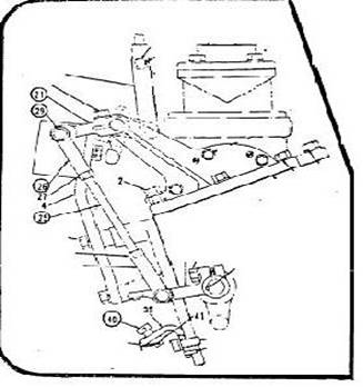
With the governor disconnected. Next, remove all of the fuel pump covers. Next, disconnect the rack linkage by removing pin No. 29 - Refer to Figure (1). Be sure to put pin No. 29 - Refer to Figure (1), back into clevis No. 26 - Refer to Figure (1), after removing the clevis from the lever No. 21 - Refer to Figure (1), to make sure it's not lost. Put the cotter pin back to make sure it doesn't fall out.
When Re-Assembling for the final time, use a new cotter pin.
Figure
(1)
You should be able to work the rack manually, by pushing and pulling on rod No. 25 - Refer to Figure (1). If the rack is hard to move, simply add a few drops of oil into the control shaft bearing holes. Working the racks up and down a few times will usually free it up.
Next, push the rack lever down a until it hits the rack stop (40) - Refer to Figure (1).Check the number of millimeters of rack travel on the injection pump nearest the governor (6R for 12 Cyl. Engines and 8R for 16 Cyl. Engines). The number of millimeters shown on this pump, is the point usually referred to as rack stop setting. It is important that this setting (Not), be changed to avoid to avoid a serious overload condition on your engine.
Using a C-Clamp, or a pair orifice grips, clamp the rack
hard against the rack stop to avoid movement. Then check each individual pump on
both sides of the engine to make sure the readings (+ .25mm). If you note more
than .25MM difference in any of the pump settings, readjust that particular
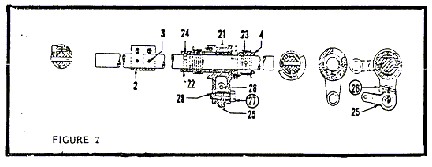
pump, using the eccentric adjustment as outlined in Figure
(2). By loosening the locking screw No.26 and turning the eccentric
adjustment No. 27 with a 5/8 open end wrench until the rack reading is within a
1/4 of a millimeter of the rest of the rack readings. While you are looking at
each individual pump, it might be a good idea to check the catalog number of the
pump to make sure that someone hasn't slipped a 15MM on an engine that is
supposed to be equipped with a 16MM pumps, or vice versa. The mixing of
different size injection on an engine is definitely NOT Advised.
 Figure
(2)
Figure
(2)
Now that the racks are equalized, we can set the valves and time the injection pump. We will need a few tools:
Screwdriver
5/16 Allen Wrench
9/16 Socket with 3/8 Drive Ratchet
7/8 and 1-1/8 Box End Wrench
Two .034 Feeler Gauges
Replacement Cover Gaskets
Although it may seem elementary, some people have trouble remembering which is the right or left side of the engine. An easy way to remember which is which. Is to imagine the engine is a Harley Davidson. You're sitting on the exhaust manifold, facing the turbocharger. The number 1 right cylinder will be the first cylinder on your right side and the number 1 left cylinder will be the first cylinder on your left side. For a 16 cylinder engine, the cylinders are numbered. Number 1 through 8 right, number 1 through 8 left.
Remove the cylinder head covers, and engage the engine barring device. Roll the engine in the direction of rotation, until the numbers on the flywheel are directly under the pointer. Stamped INJ. You will note that there are two pointers. One stamped INJ and one stamped TDC. The rotation is always from the INJ pointer to the TDC pointer, which is another easy way to tell which way to roll the engine. You will note that there are two numbers directly under the INJ pointer, separated by a line or pilot hole. For example, the numbers may say 1/8R. Since the Alco 251 is a Four Cycle engine, this means that on the first rotation of the crankshaft, the number one right cylinder will be starting injection on the next revolution. The number 8 right cylinder will be starting injection. It is necessary to find out which one of these cylinders is on the injection stroke. Because the other cylinder is on the exhaust stroke and if we are to attempt to set the injection pump on the wrong cylinder, the pump would be timed 180° out of phase, as outlined in Bulletin #1.
The easiest way to check this is to check the pushrods on both of the cylinder numbers aligned under the INJ timing pointer. The pushrods will be level and can be rotated by hand on the cylinder coming up on the INJ stroke. Another check, is to remove the INJ timing window on both pumps. The scribed line on the plunger should be very, very close to the scribed line on the body of the cylinder. whose injection pump is position to be timed.
Both the injection pump and the valves can be set on the cylinder coming up on the injection stroke, as the intake and exhaust rollers are on the base circle of the cam. It is not necessary to move the flywheel over to the TDC pointer to set the valves. Caution, remember you can only set the valves on the cylinder coming up for the injection.. To set the valves on the other cylinder, the flywheel must be rotated one full turn (360°). You will note, that the valve bridges, for both exhaust and intake have two lock nuts on each bridge. To simplify matters, from this point on, we will refer to the lock nuts closest to the exhaust manifold, as the inboard lock nuts. And the lock nuts closest to you or further away from the exhaust manifold, the outboard lock nuts.
Starting with the left valve bridge (Intake Valves), loosen the 7/8 inboard nut and the 1-1/8 outboard nut. Insert the 5/16 allen wrench into the valve bridge adjusting screw on the outboard side first (the one with the 1-1/8 nut), unscrew it about a turn and a half.. Place a .034 feeler gauge between the valve stem and the valve bridge on the outboard side. Adjust the outboard valve adjustment until .034 clearance is established. Slip the 1-1/8 combination wrench over the 5/16 allen wrench adjusting screw and tighten the 1-1/8 adjusting nut while holding the adjusting screw with the allen wrench to make sure that it doesn't move. Tighten the nut as tight as you can get it. Because these nuts will have a tendency to work loose, if not tight. Leave the .034 feeler gauge exactly where it is and take a second .034 feeler gauge and adjust the inboard adjustment in the same manner. When you finish the left side, both feeler gauges should have a moderate drag, indicating proper adjustment has been made on both valves. The key to proper adjustment is to insure that with both feeler gauges in place, neither one is to tight or to loose. This procedure gives you, effectively, an adjustment on each individual valve. If necessary, re-adjust the inboard or outboard as required to obtain the proper drag. After which, double check to make sure that the lock nuts are tight. Next, move to the right side exhaust valves and do exactly the same thing
The valves have now been adjusted on
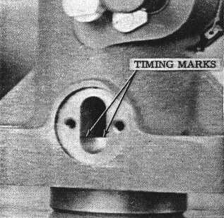
this cylinder and we can move on to check the pump timing. Remove the two top
pump timing cover screws, cover and gasket. You will note that the injection
pump is mounted at an angle, and it will be necessary for you to look into the
pump window at an angle perpendicular to the pump to insure proper alignment of
the scribe marks. You will note that there is a scribe mark on the body of the
pump inside the cover that was just removed. (See Figure 3)
 Figure
(3)
Figure
(3)
Let's assume, that you have cleaned off the scribe mark, on the side of the pump housing and determined that the pump is out of adjustment. Usually, you will find the plunger low, because of wear on the floating bushing. Should you find it necessary to adjust the fuel injection pump, remove the six cap screws on the fuel injection pump timing cover with the 9/16 socket and 3/8 drive ratchet. When you remove this cover, you will loose about a cup of lube oil, which has accumulated in the sump of the fuel pump support. So if you are picky about cleanliness, you might want to put a bucket underneath the fuel pump support, before loosening the pump timing cover to catch the oil.
To Adjust the pump, use the same 1 1/8 combination wrench we used on the valve locking nut on the outboard side, and loosen the timing adjustment lock nut. Insert the 5/16 allen wrench into the adjusting screw and adjust the pump plunger up or down until the top of the cup or the scribe line is in perfect alignment with the scribe mark on the body of the pump. Tighten the locking screw and re-check the pump to make sure the adjustment screw did not turn when you were tightening the locking screw and re-apply the timing cover using a new gasket. Before applying the timing cover, make sure the adjustment locking nut is tight.
You will note that the timing cover and gasket is made so that the bolt holes fastening the cover to the fuel pump support are slightly further away from one edge of the cover on one end. As opposed to the other. The cover should be mounted with the end of the cover where the holes are furthest from the edge of the cover, inboard, to give the gasket a little more surface area to seal against oil leaks. The cover and gasket will fit either way, so be sure the long edge of the gasket and cover, is inboard.
That takes us through the valve adjustment and injection pump timing on one cylinder. Rotate the engine in the direction of rotation until the next set of numbers comes underneath the INJ pointer and repeat the procedure as outlined above.
We usually take a piece of chalk and Mark (X) the cylinder head as we go along to make sure we don't miss any. If you know the firing order for the engine, you know exactly what cylinder is coming up next. Some of our mechanics at Waymore Power write the firing order down on a piece of scratch paper and check them off as they go. We have listed below the firing order of most standard and reverse Alco Engines for your convenience.
Standard Rotation Engines
(Counterclockwise rotation when viewed from flywheel end)
8
CYLINDER 251
1R-4L-2R-3L-4R-1L-3R-2L
12 CYLINDER 251 1R-1L-4R-4L-2R-2L-6R-6L-3R-3L-5R-5L
16 CYLINDER 251 1R-1L-4R-4L-7R-7L-6R-6L-BR-8L-5R-5L-2R-2L-3R-3L
18 CYLINDER 251 1R-1L-8R-8L-5R-5L-3R-3L-9R-9L-6R-SL-2R-2L-7R-7L-4R-4L
Reverse Rotation Engines (Clockwise when viewed from flywheel end).
8 CYLINDER 251 1L-4R-3L-2R-4L-1R-2L-3R
12 CYLINDER 251 1L-1R-5L-5R-3L-3R-6L-6R-2L-2R-4L-4R
16 CYLINDER 251 1L-1R-3L-3R-2L-2R-5L-5R-8L-8R-6L-6R-7L-7R-4L-4R
18 CYLINDER 251 1L-1R-4L-4R-7L-7R-2L-2R-6L-6R-9L-9R-3L-3R-5L-5R-8L-8R